Wednesday, August 4, 2010

Experiment 8


As we increase resistor value at the base, transistor starts to close and voltage drop increases at the Vce (emitter-collector)


Vbe require at least 0.7 volts for the transistor to work, so it doesn't change much.


With increasing the resistor at the base we we make transistor work less efficient so less (Ib) current flowing through the base and that effect the current flow through the collector-emitter (Ic), its also decrease.


Calculate Beta of this graph, Vce 1.5 volts

B=Ic/Ib=3.3miliAmps/55microAmps=0.0033/0.000055=60

At this graph i can see that 0.089volts at Vce transistor fully open (saturated), at 1.374volts at Vce its in active region, and at 2.35volts at Vce its cut off.

Monday, August 2, 2010

Experiment 7


o.8 Volts volt drop across base and emitter of transistor indicates that its working and in saturated condition as it requre at least 0.7 volts to work.


54.1 mVolts voltage drop across collector and emitter means that transistor is fully open.


This graph shows working areas od BJT transistor. Area marked with A is a saturated region, which means that BJT fully on, and area marked B is a cut off area, which means it fully off.

The more voltage drop at the base of transistor, the less voltage drop at emitter-collector of transistor, it means that if more " fully on".

Power dissipation at 3 volts Vce.

P=Ic*Vce=3volts*0.014=o.o42 watts= 42 mWatts.

Calculate Beta of this transistor at Vce 2,3,4 volts

B=Ic/Ib

At 2 volts Vce B=21/0.75=28

At 3 volts Vce B=12.5/0.52=26

At 4 volts Vce B=5.5/0.22=24

Beta is how much Ic signal amplified compare to Ib.

Experiment 6

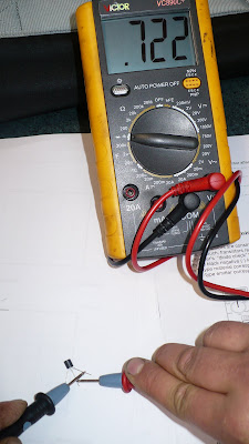
Emitter-base always have slightly higher forward voltage drop then collecter-base, so can be identified easy with multimeter.
NPN transistor:


PNP transistor

Thursday, July 29, 2010

Experiment 5


Here is some oscilloscope graph which shows charging time of the capacitors as mili seconds cant be observed visually


Oscilloscope
reading of 500 msec


Oscilloscope
reading of 50 msec


Oscilloscope
reading of 235 msec


Oscilloscope
reading of 1650 msec


Bigger capacitors takes more time to charge to full then smaller capacitors and also resistors can restrict current flow if installed in circuit and effect charging time of capacitor.

Experiment 4

Vs=10 & 15 volts, R=1 kohm, 1 x Zener diode, 1 x diode

Zd=5.1 volts
D=0.7 volts

----------------At 10 volts------------------------------At 15 volts

Volt drop V1=4.68 volts_______________________4.83 volts
Volt drop V2=0.67 volts_______________________0.69 volts
Volt drop V3=5.34 volts_______________________5.52 volts
Volt drop V4=5.22 volts_______________________9.83 volts

Current amps at 10 volts Vs
I=V/R=(10-5.1-0.7)/1000=4.2 mili amps

Current amps at 15 volts Vs
I=V/R=(15-5.1-0.7)/1000=9.2 mili volts


When zener diode installed in reverse bias it takes 5.1 volts to run and let the rest through and another diode installed in forward bias, takes 0.7 volts to run and let the rest through so voltage drop across two diodes would be 5.1+0.7=5.8 volts, it doest matter how much voltage applied as they will act with the same voltage drop, until voltage would be so high it just push thorough the diodes and damage them.
Voltage drop across resistor indicates how much voltage let for it to use.

Tuesday, July 27, 2010

Experiment 3

Components: 2 x resistors, 1 x 5V1 400mW Zener Diode


R= 100 ohm, RL= 100 ohm, Vs=12 volts


Vz value

Vz=4.98 volts at Vs=12 volts

Vary Vs from 10V to 15V

At 10V, Vz=4.81 volts

At 15V, Vz=5.1 volts

Explanation:

In this circuit zener diode in reverse bias takes maximum 5.1 volts to work and let the rest through to negative side of the circuit, so only 5.1 volts available for the second resistor in parallel with zener diode.

Such circuit can be used for voltage regulator.


Now we reverse polarity of zener diode and value of Vz now 0.853 volts and zener diode now in forward bias and needs around 0,8 volts to work so it takes 0.8 volts and let the rest through.

Thursday, July 22, 2010

Experiment 2


---------------------Voltage drop in forward -------------Voltage drop in reverse
LED-----------------1.761 volts---------------------------0 volts
DIODE--------------0.541 volts---------------------------0 volts

LED cathode side got shorter wire and flat side, and diode cathode side marked with grey stripe.


R=1000 ohm __________ V=5.31 v _________ Vd=0.657v

Calculated amps____________________________Measured

5.31-0.657=4.653___________________________4.6 mili amps

I=4.653/1000=4.653 mili amps


Its a voltage drop of 0.657 volts at diode as it use this voltage to run.


Calculated voltage drop--------------------------Measured voltage drop


Va=5.31-----------------------------------------0.664 volts


I=4.653 ma


R=1000 ohm


V=IxR=4.563*1000=4.563 volts


Vd=Va-V=5.31-4.653=0.657 volts

Max value of current that can flow through diode


1 amp at 75 C degrees


For R=1000 ohms, what is max Vs


Vs=1amp*1000ohms=1000 volts


Now diode replaced with LED


Calculated current amps-----------------------------Mesured current amps


Vs=5.31 volts----------------------------------------3.3 mili amps


Vd=1.967


V=Vs-Vd=3.343

I=V/R=3.343/1000=3.343 mili amps


LED light voltage drop was hiher then diode, and as it takes more voltage to run, then less amps flow through LED.